
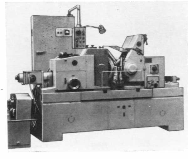
Special longitudinal milling machine series 6940
The machines are destined for high production machining the vertically positioned flat surfaces on the workpieces from ferrous metals. They successfully substitute the universal longitudinal milling and special pedestal machines.
The machines having inclination of a spindle axis at various angles to a table working surface are delivered upon request.
Design features:
- change of A dimension is executed by turn of a spindle box with following clamping. Travel and clamping are made manually;
- the guides are play-free, clad with fluoroplastic;
- mechanisms of feeds: roll-screw pairs or rack-gear;
- manual movement of the stocks by one handwheel, on a two-side machine – each stock separately or both together;
- the machines are equipped with clamping device upon request;
- utomatic machining cycles.
Composition of machine:
- table;
- beds (two sets);
- bridge (slide and legs – two sets and cross bar);
- milling stock (sledge and sliding block);
- 2-coordinates head with electric spindle;
- universal 2-coordinates head;
- four chip conveyors;
- operator’s cab with control board;
- electric equipment with CNC device;
- mechanism for automatic tool change (is not shown on drawing).
Version
|
Model |
Table,mm |
А, мм
|
В, мм
|
|
6942-02, 03
|
800 х 1500 |
225 ... 675
|
230 ... 48 |
|
6942-02, 03
|
1000 х 2000
|
225 ... 675
|
350 ... 600
|
|
6942-02, 03
|
1250 х 2500
|
225 ... 675
|
450 ... 700
|
|
6942-02, 03
|
1500 х 3000
|
225 ... 675
|
630 ... 880
|
Technical characteristics
|
Machine |
6942 |
6943 |
6944 |
6945 |
|||||
|
Version |
03 |
02 |
03 |
02 |
03 |
02 |
03 |
02 |
|
|
Main drive power, kW |
15..45 |
2х15..45 |
15..45 |
2х15..45 |
15..45 |
2х15..45 |
15..45 |
2х15..45 |
|
|
Spindle torque, Nm |
For all the machines 8000 |
||||||||
|
Diameter of end |
For all the machines From 160 up to 400 mm |
||||||||
|
Travel of table, mm |
1450 |
1450 |
From 2000* |
From 2000* |
From 2500* |
From 2500* |
From 3000* |
From 3000* |
|
Design features
Table 1. has been placed and fixed on a foundation of machine. Openings for chip withdrawal can be provided in a table. Customer’s requirements for table design, for quantity and disposition of the openings and the slots on a table working surface are specified when signing a contract.
A bridge (X coordinate) consisting of two slides with the legs fixed on them which are joined by a cross bar moves on two beds 2. placed on two sides of machine.
Milling stock 5. consists of a sledge and a sliding block. A sledge moves in the horizontal direction (Y coordinate) on the female guides of a cross bar which has O-section in the horizontal plane. A sliding block has the vertical movement (Z coordinate) on the sledge guides. A sliding block is hydraulically balanced.
Two interchangeable heads (5 and 6), each of them has a turn about Z axis (C coordinate) and a turn about Y axis (B coordinate), can be installed on a sliding block flank in turn.
A control board and an operator’s place are in a mobile cab 8. An operator a control board are protected from chip by an armored glass. Installation of a video camera with a monitor installed in an operator’s cab is possible for watching a part of a cutting zone.
A portal (X) moves from the synchronized multimotor friction mechanisms of the feeds constructively joint with the guides of a bed.
A sledge (Y) and a sliding block (Z) of a milling stock have the self- contained feed drives from the reducers, final segment – ball-screw pair. The guides sliding block – sledge and sledge – cross bar are rolling or combined ones.
Feed drives of the two-coordinates heads rotation at each coordinates (B and C) from the reducers, final segment – the gears having clearance adjustment or a worm – worm-wheel. The guides are rolling or combined ones.
The guides and the final segments have a reliable guard.
The chip withdrawal conveyors (7) have been installed between the beds and a table (at the request of a customer can be installed under a table having the openings for chip withdrawal on its working surface).
Oiling of all the guides is dosed periodic.
Electric equipment of machine
Electric equipment of Siemens Co. is presumed to install on a machine.
The alternate current motors with digital control of frequency converters are installed in the main drives and the feed drives (X(X1 and X2), Y, Z, B and C).
Sinumerik 840C(D) CNC system in a set with a main control board, manual control board, color display 14" and necessary assortment of options provides:
- simultaneous machining at five coordinates;
- synchronization of travels at coordinates X(X1 and X2);
- measuring a detail using the transducers of Renishaw Co.;
- interface for data input from a personal computer;
- error reduction when travelling at the coordinates.
Feedback sensors of Heidenhain Co. are used in a machine.
Control mode – CNC and universal (F4 and F!).

